Communication Protocols
- Raveen Pabasara
- Jul 10, 2023
- 10 min read
Updated: Jul 10, 2023
Today we'll talk about Arduino communication methods. Devices must interact with one another in order to convey environmental information, indicate changes in their statuses, or request auxiliary activities. With any serious hobby electronics work, you're certain to come into one or more of the major communication protocols in use, whether it's when dealing with different sensors or modules like the ESP8266. In this lesson, we intend to present and explain the typical communication protocols used by electrical devices using the Arduino Uno.
Binary and Number Systems Explained
Before delving into communication protocols, it's important to understand how digital signals are transmitted between devices. In a digital signal, data is conveyed through rapid switches between high and low voltage levels. These highs and lows represent binary values of 1s and 0s, respectively. When combined in a specific sequence, these bits form information that can be interpreted by microcontrollers. Think of these bits as the building blocks of data, and when grouped in sets of eight, they are referred to as bytes.
A byte can be visualized as a sequence of 1s and 0s, such as 10111001. Similar to how a number like 597 is composed of place values (hundreds, tens, ones), each digit in a byte represents a place value, and the presence of a 1 or 0 in that place value determines its contribution to the overall value.
In the case of 597, the digit 5 indicates five hundreds, the digit 9 represents nine tens, and the digit 7 stands for seven ones. When these place values are added together (500 + 90 + 7), the result is five hundred ninety-seven. This counting system, where each digit can have values from 0 to 9, is known as the base 10 system or decimal system.
Now let's return to our number 10111001. Since each digit in this number can have values of 0 or 1, we can infer that it is in the base 2 system, also known as binary. In the binary system, each digit represents a power of 2. Therefore, 10111001 can be calculated as 1 * 2^7 + 0 * 2^6 + 1 * 2^5 + 1 * 2^4 + 1 * 2^3 + 0 * 2^2 + 0 * 2^1 + 1 * 2^0, which equals 185 in decimal.
Apart from the base 10 and base 2 systems, mathematicians have defined other commonly used number systems, such as base 8 (octal) and base 16 (hexadecimal). Each number system follows the same principle, where each digit represents a multiple of a power of the base. The value of each digit can range from 0 to base-1.
Understanding different number systems is valuable because bytes and data are often represented in various ways. For instance, it's easier to write "B9" in hexadecimal than "10111001" in binary. In software, binary numbers are prefixed with "0b," octal numbers with "0," and hexadecimal numbers with "0x." Decimal numbers, however, are not prefixed.
Knowledge of base conversions is also beneficial as representing numbers in binary can lead to interesting mathematical tricks. However, for the purpose of this tutorial, we will keep our focus on this fundamental understanding. Feel free to explore the appendix attached to this tutorial for articles on these mathematical tricks.
3 protocols : UART, SPI, and I2C
To assure device interoperability, the electrical engineering community chose to standardize electronics around three communication protocols. By basing devices on a few protocols, designers could communicate with any device by understanding a few basic notions about each communication protocol. These three protocols, UART, SPI, and I2C, differ in implementation but ultimately serve the same purpose: high-speed data transmission to any compatible device.
1. UART Communication Protocol
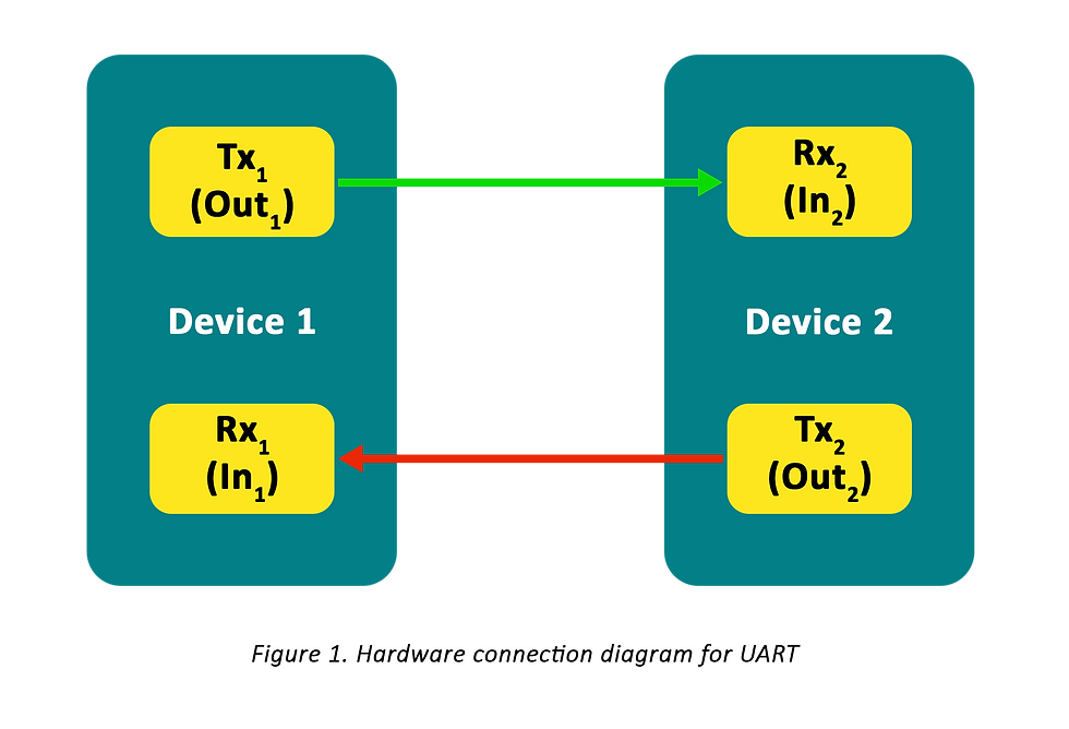
The first protocol we'll look at is Universal Asynchronous Receiver/Transmitter (UART). Because data is transferred in consecutive bits, UART is a type of serial communication (more on this later). The cabling for UART communication is quite simple: one line for transmitting data (TX) and one line for receiving data (RX). The TX line, as you might assume, is used to send data to the device, while the RX line is used to receive data. The TX and RX lines of a serial communication device constitute a serial port via which communication can take place.
The word UART really refers to the onboard hardware that handles serial data packing and translation. This hardware is required for a device to interact via the UART protocol! The Arduino Uno has one serial port for communicating with the computer to which it is attached. That's correct! The USB (Universal Serial Bus) port is a serial port! This USB connection is separated out by inbuilt circuitry on the Arduino Uno into two digital pins, GPIO 0 and GPIO 1, which can be utilized in projects involving serial communication with devices other than the computer.
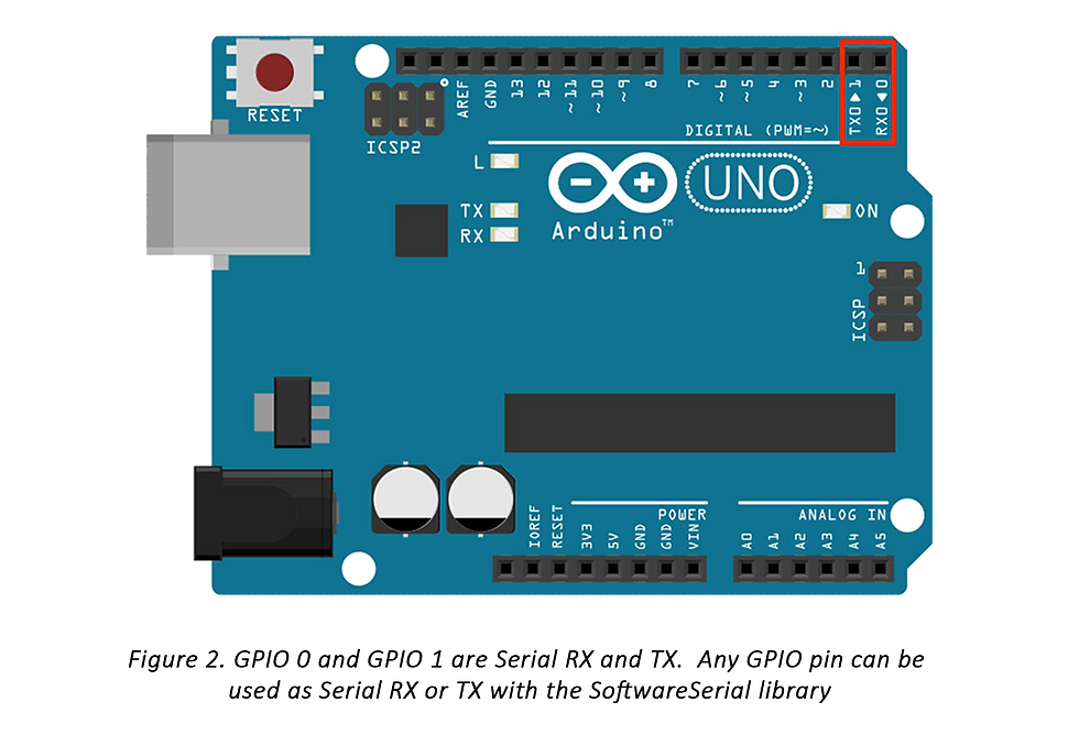
Other GPIO pins can be used as Serial RX and TX lines by using the SoftwareSerial Arduino library (SoftwareSerial.h).
Asynchronous communication is referred to as UART because it does not rely on a synchronized clock signal between the two devices seeking to communicate with one other. Because the connection speed is not determined by this constant signal, the "sender" device cannot be sure that the "receiver" device receives the right data. As a result, the devices divide data into fixed-size pieces to verify that the data received matches the data supplied.
The UART data packet appears to be as follows:
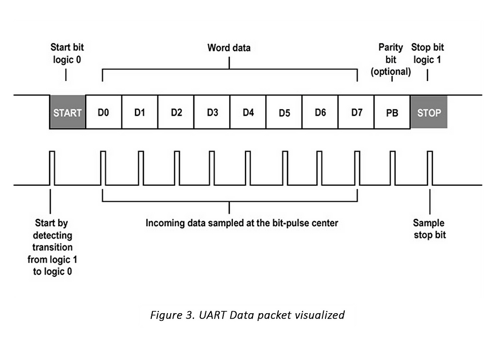
UART communication involves the transmission of packets with predefined sizes that include additional information to indicate the start and end of a message, as well as confirmation of its successful reception. However, due to this overhead, UART is slower compared to synchronized forms of communication, as a significant portion of the transmitted data is dedicated to the communication process itself rather than the application data.
Fortunately, when working with embedded platforms like Arduino, implementing UART serial communication does not require dealing with the low-level details at the bit level. These platforms typically provide higher-level software libraries that simplify the communication process for users. In the case of Arduino, users can utilize libraries such as Serial and SoftwareSerial to easily implement UART communication in their projects.
To facilitate the understanding of Arduino Serial and SoftwareSerial usage, here is a concise C++ reference for initializing and using these libraries.
UART communication is specifically designed for point-to-point communication between two devices, and it lacks the capability to differentiate between multiple devices sharing the same communication line. When multiple devices attempt to transmit data simultaneously, a phenomenon known as bus contention occurs, resulting in the reception of garbled and unusable data by the receiving devices. This limitation highlights the need for proper coordination and synchronization among devices sharing the UART communication line.
Additionally, UART operates in a half-duplex mode, meaning that data can be transmitted bidirectionally, but not simultaneously. In practical terms, this implies that only one device can "talk" or transmit data at any given time. While this may appear as a constraint, it is generally not a significant disadvantage for most applications that employ UART communication. Proper communication protocols and mechanisms can be implemented to manage data transmission and ensure efficient coordination between the communicating devices.
2. SPI Communication Protocol
The next communication protocol we’ll cover is Serial Peripheral Interface (SPI). SPI is different from UART in several key ways:
Synchronous
Follows a master-slave model, where there is one master device and multiple slave devices
More than two lines required for implementation
The hardware connection diagram for SPI is slightly more complicated, and looks something like this:
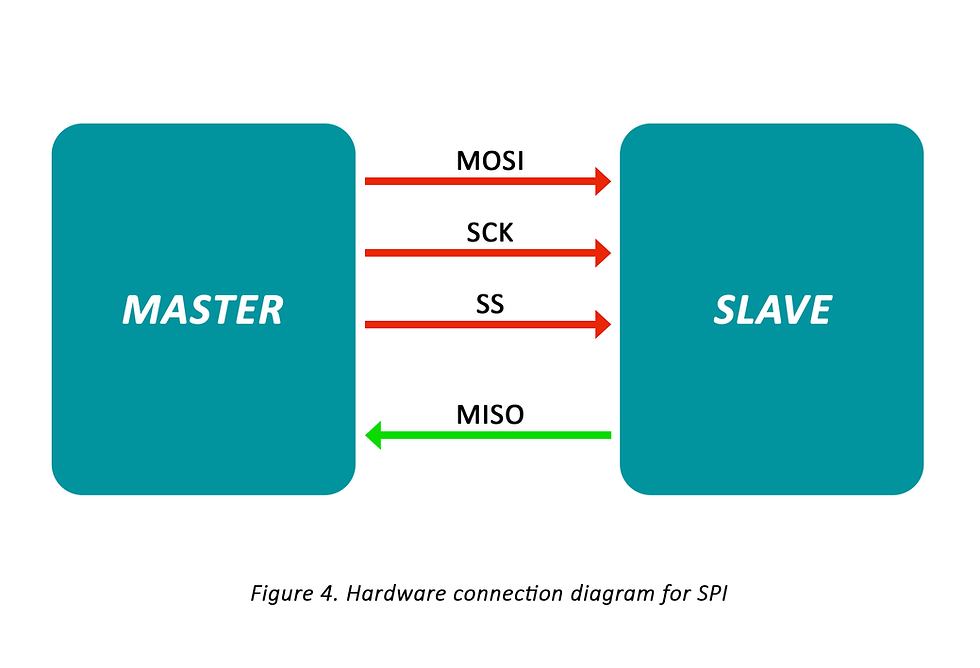
⏺ MOSI (“Master Out Slave In”) : Data transmission line from master to slave
⏺ SCK (“Clock”) : Clock line defining transmission speed and transmission start/end characteristics
⏺ SS (“Slave Select”) : Line for master to select a particular slave to communicate with
⏺ MISO (“Master In Slave Out”) : Data transmission line from slave to master
The first thing to notice about SPI is that it operates on a master-slave architecture. This implies that communication is based on designating one device as the master and the other devices as slaves. This creates a hierarchy among the devices, indicating which device is "in control" of the others. This master-slave concept will be discussed further when we provide a sample communication between a master and slave device.
As previously stated, several slaves can be linked to a single master device. A hardware schematic for such a system may look like this:
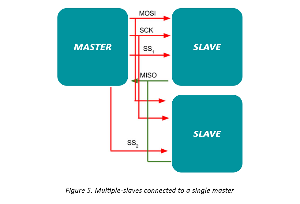
SPI communication does not require separate transmit and receive lines for each slave connected to the master. Instead, a single common receive line (MISO) and a single common transmit line (MOSI) are shared among all the slaves and the master. A common clock line (SCK) is also used for synchronization. The master device determines which slave it communicates with through dedicated Slave Select (SS) lines for each slave. As a result, adding more slaves to the system requires additional GPIO pins on the master's side.
SPI communication is synchronous, meaning that it relies on a clock signal generated by the master device. The clock signal sets the pace of communication between the master and the slave devices. The master determines the communication speed by controlling the clock signal, and the slaves respond by communicating at that specified speed. This flexibility allows the master to choose any communication speed within the limits supported by the slave devices.
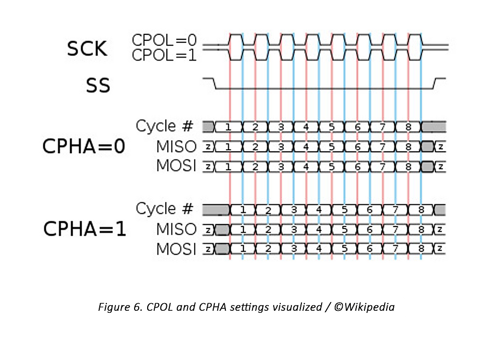
The clock signal in SPI has two important characteristics: clock polarity (CPOL) and clock phase (CPHA). CPOL defines the idle state (either low or high) of the clock signal when there is no active communication. Devices often put the clock line in the idle state to conserve power. CPHA determines the clock edge (rising or falling) at which data is captured. Depending on the CPHA setting, data is captured either on the rising or falling edge of the clock signal.
There are four distinct combinations of CPOL and CPHA that determine the behavior of SPI communication, and they can be summarized in a table.
Wikipedia does a great job graphically representing the CPOL and CPHA settings and their relationship to the data being transmitted!
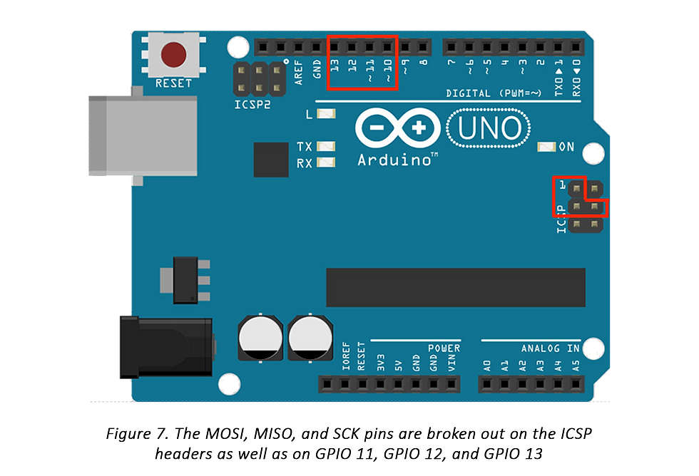
We'll now concentrate on SPI implementation on the Arduino, with the Arduino serving as the master device (SPI.h). On Arduino boards, the SPI digital pin connections for SCK, MOSI, and MISO are preset. The connectors for the Arduino Uno are as follows:
SCK: GPIO 13 or ICSP 3
MOSI: GPIO 11 or ICSP 4
MISO: GPIO 12 or ICSP 1
SS: GPIO 10
Any digital pin can be also used for the SS pin. To select the device, this digital pin must be driven low.
Here’s a brief C++ reference for Arduino SPI initialization and use.
Because SPI is full-duplex, communication is always bidirectional, even if the application only requires data transfer in one direction. A shift register is typically used to provide SPI full-duplex data transmission. (A shift register instruction is included in the appendix!) This means that as each bit is read, the bits before it are moved by one position. The first bit is then popped and passed back to the other device through the SPI connection!
3. I2C Communication Protocol
Because SPI is full-duplex, communication is always bidirectional, even if the application only requires data transfer in one direction. A shift register is typically used to provide SPI full-duplex data transmission. (A shift register instruction is included in the appendix!) This means that as each bit is read, the bits before it are moved by one position. The first bit is then popped and passed back to the other device through the SPI connection!
The ability to connect multiple masters to multiple slaves
Synchronicity (just like SPI), which means higher speed communication
Simplicity: implementation only requires two wires and some resistors
I2C is a two-wire interface used for communication between devices. It relies on a data line called SDA and a clock line called SCL. In its idle state, both the data and clock lines are pulled high. When data needs to be transmitted, the lines are pulled low by the devices involved using MOSFET circuits. It's important to note that I2C operates in an open-drain configuration, meaning that the devices can only pull the lines low but not drive them high. To ensure proper operation, pull-up resistors (typically around 4.7kΩ) are necessary to pull the lines high when no devices are actively transmitting data. This ensures that the lines are in the desired idle state.
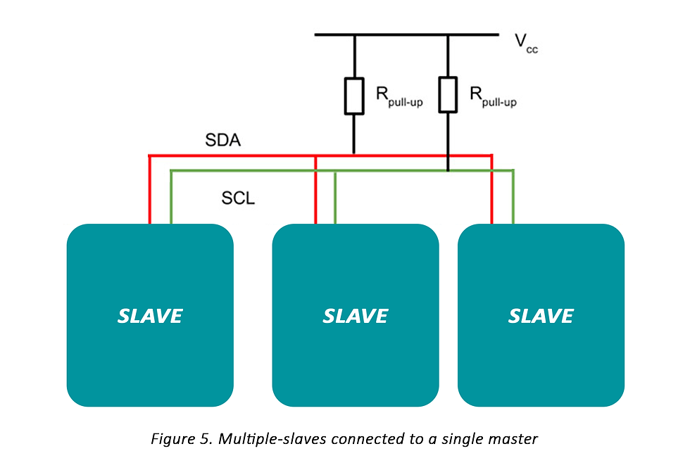
I2C is unusual in that it addresses the problem of interacting with numerous slave devices. I2C communication, like SPI communication, uses a master-slave concept to construct the "hierarchy" of communication. Instead than selecting slaves through distinct digital lines, masters choose slaves based on their unique byte addresses. These addresses may look like this: 0x1B. This implies that adding more slaves to a master will not necessitate the use of more digital lines. The program will be able to separate slaves based solely on their addresses as long as each slave has a unique address. Consider these addresses to be names. The master just calls a slave's functionality by name, and only that slave answers.
The address and data portions of the I2C communication line might look something like this.
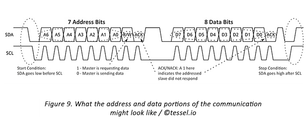
The ACK (acknowledge) and NACK (not acknowledge) bits on the communication line in I2C indicate whether the addressed slave responds to the communication. They serve as a way to periodically check if the communication is functioning as expected. These bits do not carry address or data information but have minimal impact on the overall communication time compared to start and end bits and pauses in UART protocols.
In I2C, slaves have the flexibility to define their own communication requests. Different slaves may require specific bytes to be written over the SDA line in a particular order to write to or request information from them. For instance, in some accelerometer modules, specific bytes are written to indicate which hardware register the master wants to read before making any read requests. To understand these specifications, it is necessary to consult the datasheets of the individual slaves to obtain device addresses, register addresses, and device settings.
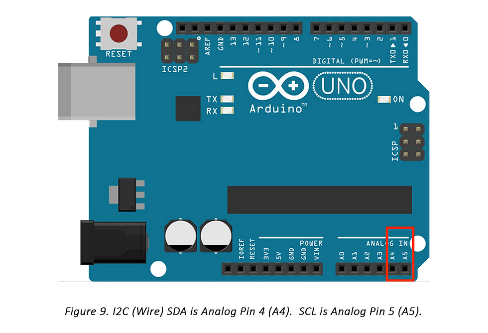
The Arduino facilitates I2C implementation through the Wire library (Wire.h). It allows the Arduino to be configured as either an I2C master or slave device. In the case of the Arduino Uno, the I2C connections are established as per the following configuration.
SDA: Analog Pin 4
SCL: Analog Pin 5


Comments